Bulletin 40: Thermal Design of Hairpin Heat Exchangers
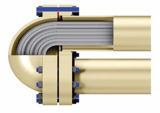
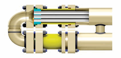
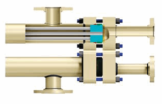
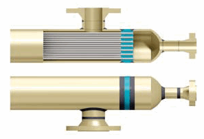
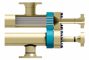
PETROFIN® Patented Closure
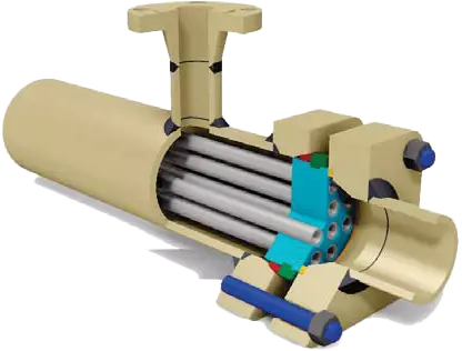
- The Holland Petrofin closure has fewer parts, is the simplest to install and disassemble, and is the most efficient seal on
the market. Only two flanges are needed to secure both shell and tube seals. No other manufacturer does this with comparable results. - With one expendable seal for the shell side and one expendable seal for the tube side, there is an absolute guarantee against interstream leakage.
- There is only one reusable locking split ring that is in full view and is the simplest of all to remove and install.
- Closures flanges on low pressure units up to 6” shell size area a square, 4-bolt design. Larger units and high-pressure smaller units have circular closure flanges with additional bolting. Through-bolted closures are not standard on 6” and smaller units, but are available upon request.
- Tube bundles are easily removed and do not require disassembly of either the shell piping or mountings. Only five standard interchangeable replacement parts are required for reassembly after routine cleaning and maintenance. These are the rear cover gasket, sealing rings, and tube gaskets. Most sizes are stocked for immediate replacement.
- Our unique closure allows for more tubes in a given shell size resulting in more heat exchange for the same competitive price.
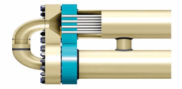
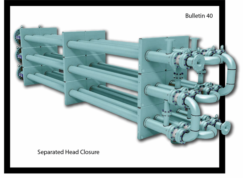
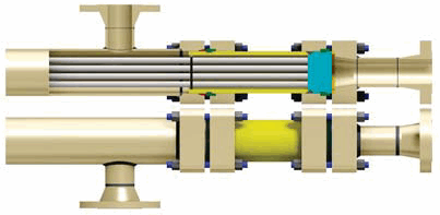
Separated Head Closure
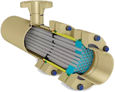
- The Holland Separated Head Closure has separate flanges and bolting for each sealing surface.
- With one expendable seal for the shell side, one expendable seal for the tube side, separate flanged and bolted joints for each sealing surface, this closure can handle all applications in severe service.
- This closure is recommended for pressures above 2000 psig, cyclic services, low-temperature service, extreme temperature differentials and hard to hold fluids.
- Tube bundles are easily removed and do not require disassembly of either the shell piping or mountings. Only five standard interchangeable replacement parts are required for reassembly after routine cleaning and maintenance. These are the rear cover gasket, sealing rings, and tube gaskets. Most sizes are stocked for immediate replacement.
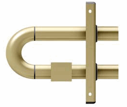
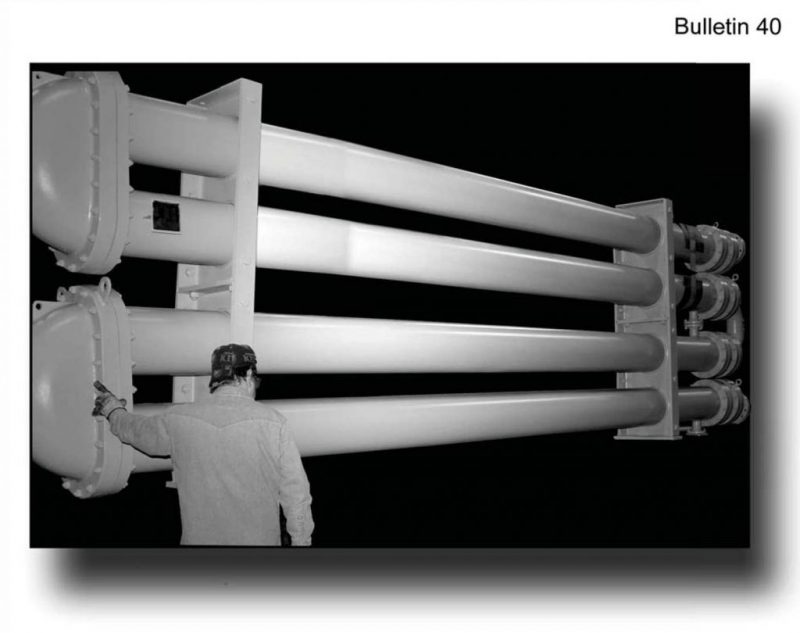
The Holland Hairpin Heat Exchanger
- All Holland hairpin heat exchangers are ASME inspected, code stamped and National board registered.
- Multiple sections can be shipped completely assembled and ready for one inlet and outlet process piping connection.
- Our longitudinal fintubes are produced by an electric resistance welding method, which assures high heat transfer efficiency throughout the life of the equipment.
- Holland hairpin heat exchangers are available in a wide range of sizes to meet most process requirements. See pages 4 and 5 for the many standard design double pipe and multi-tube hairpin exchangers that are available.
- R.W. Holland’s standard designs reduce costs of engineering, thermal design, drafting, and shop fabrication. Although we offer standardized designs whenever possible, we custom engineer equipment to meet process or piping requirements. A few of our customers modifications are shown in this brochure.
Advantages of the Hairpin Heat Exchanger
- There are two types of hairpin heat exchangers.
- Double pipe section with one tube, either finned or bare, within the shell pipe.
- Multi-tube section with smaller tubes, either finned or bare, within the shell pipe.
- Hairpin heat exchangers operate in true counter current flow permitting extreme temperature crossing. The full log mean temperature difference can be utilized without reducing correction factors generally necessary in shell and tube exchangers. The larger temperature difference decreases surface requirements and cost.
- Due to their modular concept, hairpin heat exchangers are economically adaptable to service changes. Changing duties are met by merely rearranging, adding, or subtracting sections. Shell and tube exchangers frequently have to be scrapped and new exchangers ordered when duties change.
- The hairpin exchanger is ideal for wide temperature ranges and differentials. Because of the U-tube construction, expensive expansion joints are not required. Hairpin heat exchangers are not susceptible to tube-to-tubesheet weld cracks due to thermal stress. The thermal gradient of a tubesheet on a hairpin heat exchanger is through the thickness of the tubesheet as apposed to across the tubesheetface, as in multi-pass shell and tube exchangers.
- Hairpin deliveries are shorter than shell and tube due to the standardization of design and construction.
Design Your Own Exchanger
The purpose of the following article is to describe the basic heat transfer laws, and a simple method to thermally estimate hairpin heat
exchangers. But first, the advantages of each type should be mentioned.
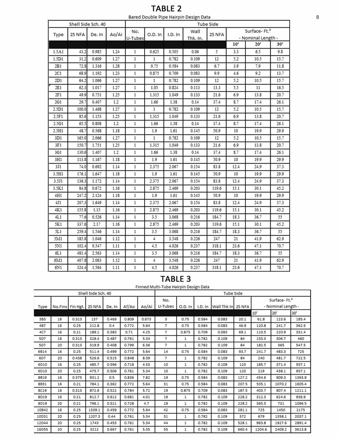
BARE DOUBLE PIPE & BARE MULTITUBE HAIRPIN
(Table 2 & 4)
- High Pressure:
- Capable of carrying the maximum pressure allowed by ASME Code per given wall thickness (Up to 14600 psi with no corrosion allowance)
- Higher pressure ratings are possible using materials with higher stress values
- Low and Moderate Surface Requirement:
- Doublepipe (surface ≤ 60 ft²)
- Multitube (surface 60 to 1000 ft²)
- Excessive Fouling:
- Bare tube for processes that require frequent mechanical cleaning
- Ease of cleaning and accessibility
- Low Pressure Drop:
- Bare tube exchangers offer least pressure drop among most exchangers
- Adopting New Application:
- Hairpin for process that might be modified or completely changed
- Accommodate these changes simply by rearranging the sections.
- One or more sections might be added or removed
- Cooling Viscous Fluid on Shell Side:
- Bare tube good for cooling viscous fluids
- Viscosity on fin wall is higher than bulk average viscosity, producing a lower film coefficient on fin, thus impeding heat transfer and causing excessive fouling.
Please note that unlimited numbers of bare tube sections could be arranged in parallel and series to fit a specific application.
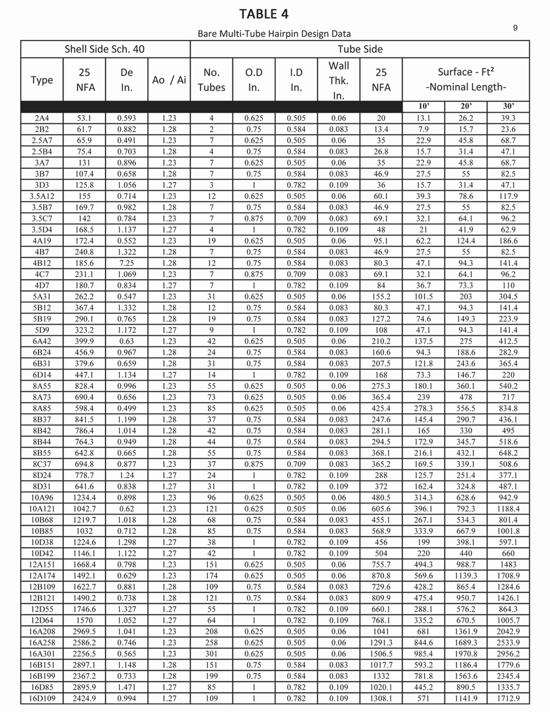
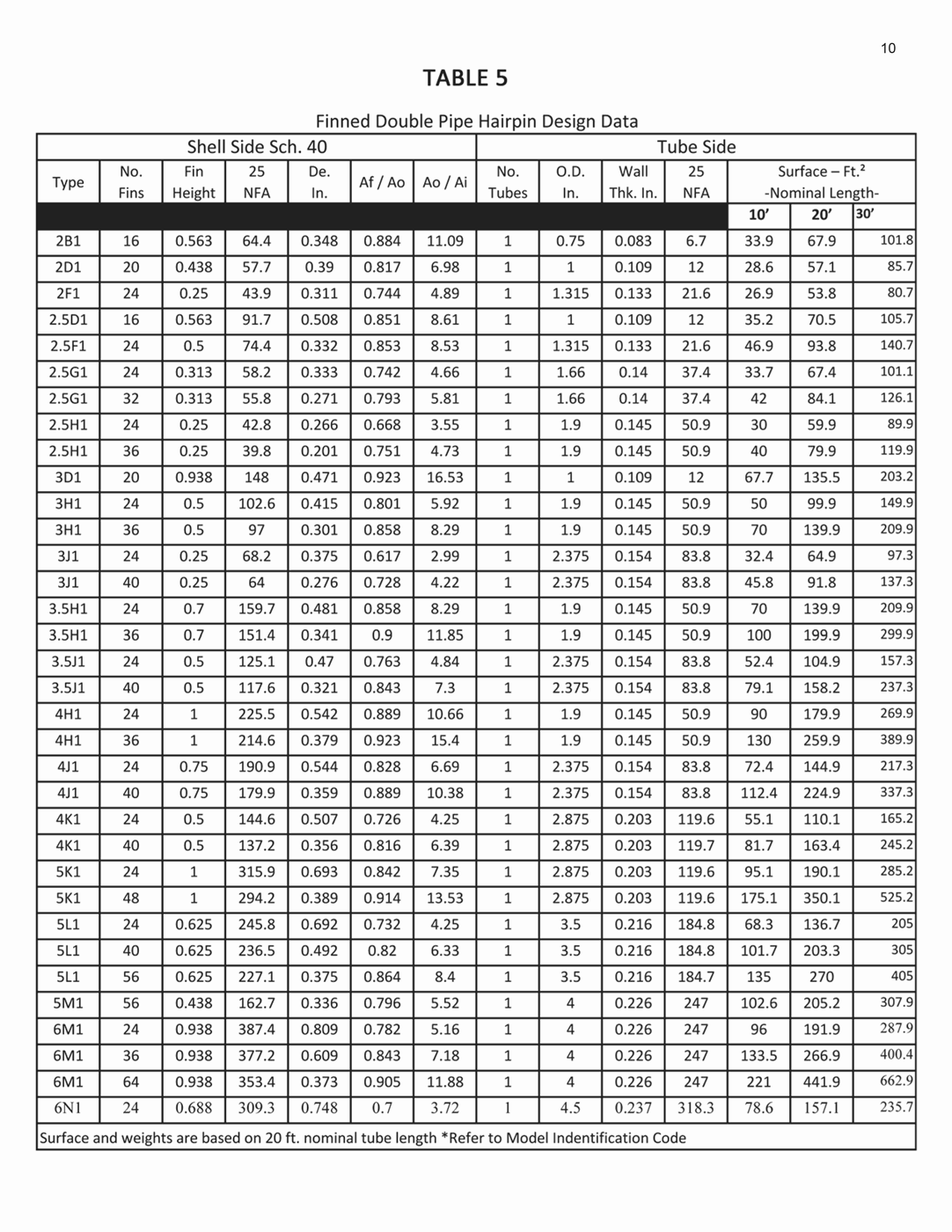
FINNED DOUBLE PIPE & FINNED MULTITUBE
(Table 3 & 5)
- High Pressure:
- Offers same advantages for high pressure as bare tube Hairpin
- High Surface Requirements:
- More advantageous when shell side heat transfer coefficient is low
- Finned Hairpin has two to five times heat transfer surface than bare tube Hairpin
- Heating a Viscous Fluid on the Shell Side:
- High shell side viscosity results in low heat transfer coefficient, requiring more heat transfer surface
- Holland’s finned Hairpins are designed with these problems in mind
- Heating and Cooling Gases:
- Low transfer rate of gases makes finned hairpin an attractive selection
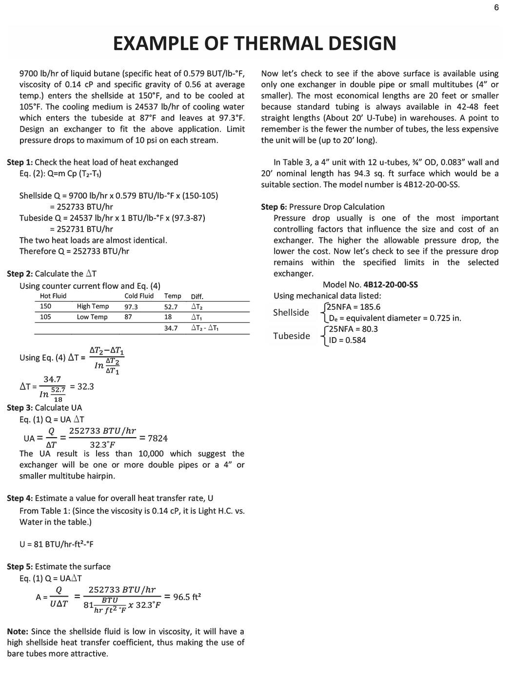
Thermal Design Procedure
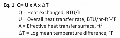
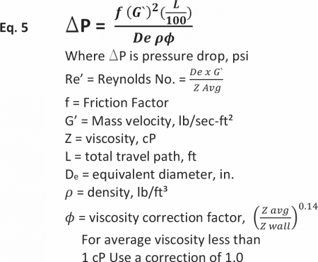
Heat Transfer: The basic heat transfer law for the exchange of heat between two fluids is best described by the equation:
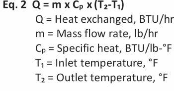
The heat load or heat exchanged may also be expressed as the product of mass flowrate, specific heat, and temperature change in each stream.

is the overall heat transfer rate which is the sum of the
total resistance to heat transfer. *U is best described by:
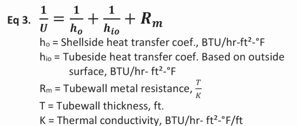
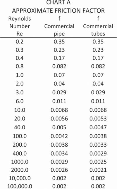
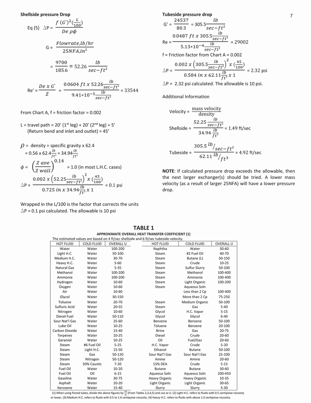
*Table 1 shows the approximate U limits that have been calculated under different conditions. Please note that these values are based on 4 ft/sec shellside and 6 ft/sec tubeside velocity. An overall fouling factor of 0.004 and 5-10 psi pressure drop on each stream has been assumed.

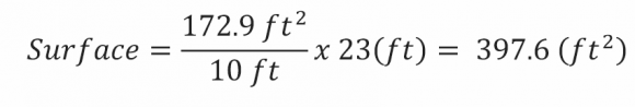
is the effective heat transfer surface; which is found from Table 2, 3, 4 and 5 for different types of Hairpin exchangers. To estimate surface for lengths that are not listed, simply use the following formula:
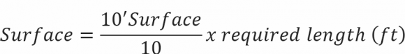
Example: Using Table 3 to find the 10’ surface, an 8” shell with 44 U-tubes, 3/4” OD, 23’ nominal length has a surface of:

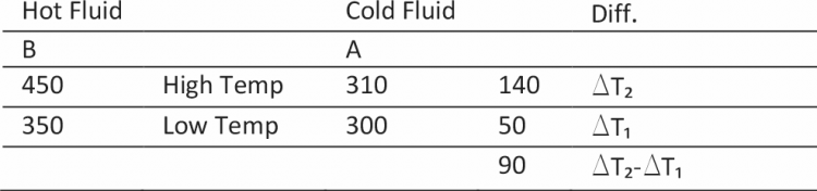
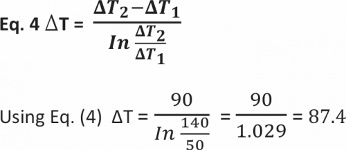
is the log mean temperature difference. One of the biggest advantages of Hairpin exchangers is the ability to have a true counter-current flow of streams. This allows the hottest portion of the hot stream to be in contact with the hottest portion of the cold stream at any given time. This eliminates the need for any temperature correction factor.
Example: Let’s assume that fluid A enters the shellside at 300°F. Fluid B enters the tubeside at 450°F and is to be cooled down to 350°F.
Now that all the parameters of Eq. (1) have been defined, a concept called UA analysis should also be defined. Let’s refer to Eq. (1):
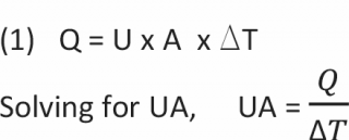
Q is easily found by using Eq. (2), DT is calculated using Eq. (4) Please refer to the guidelines in the selection of bare vs. fin tube.
IF UA < 10,000
doublepipe or multitube 4” shell or under
IF 10,000 < UA < 50,000
4”, 5” or 8” multi-tube shells or several doublepipe in series and/or parallel.
IF 50,000 < UA < 100,000
10” or several 6” or 8” multi-tube shells in series and/or parallel arrangements.
IF 100,000 < UA < 150,000
12”, 14” or 16” multitube or several 8” or 10” multi-tube shells in series and/or parallel arrangement
R.W. Holland Offers Flexibility to Meet Customer Applications And Specifications
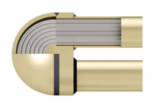
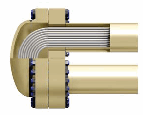
Tube End Closures
Return End Closures